 СКБ ИС
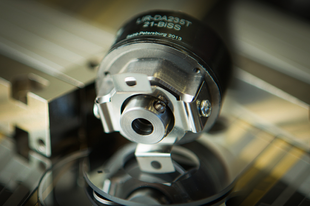
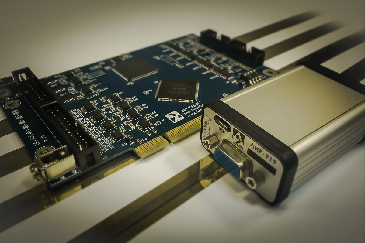
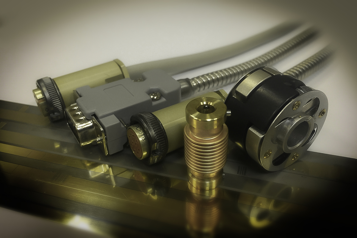
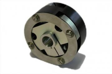
Высокоточный абсолютный оптоэлектронный преобразователь угловых перемещений (абсолютный энкодер).
Диаметр корпуса 90 мм, диаметр цельного вала 10 мм или 14 мм (для совместной эксплуатации с торсионной муфтой ЛИР-805), разрешающая способность - до 16777216 позиций на обороте (до 24 бит), напряжение питания +5 В.
Последовательный интерфейс SSI RS422. Точная механика и оптика позволяют минимизировать погрешность до ± 3,5".
Предназначен для установки на поворотные столы металлообрабатывающих станков, для применения в радиоастрономии, радиолокации и прочих областях, где недостаточно разрешающей способности и точности общепромышленных энкодеров.

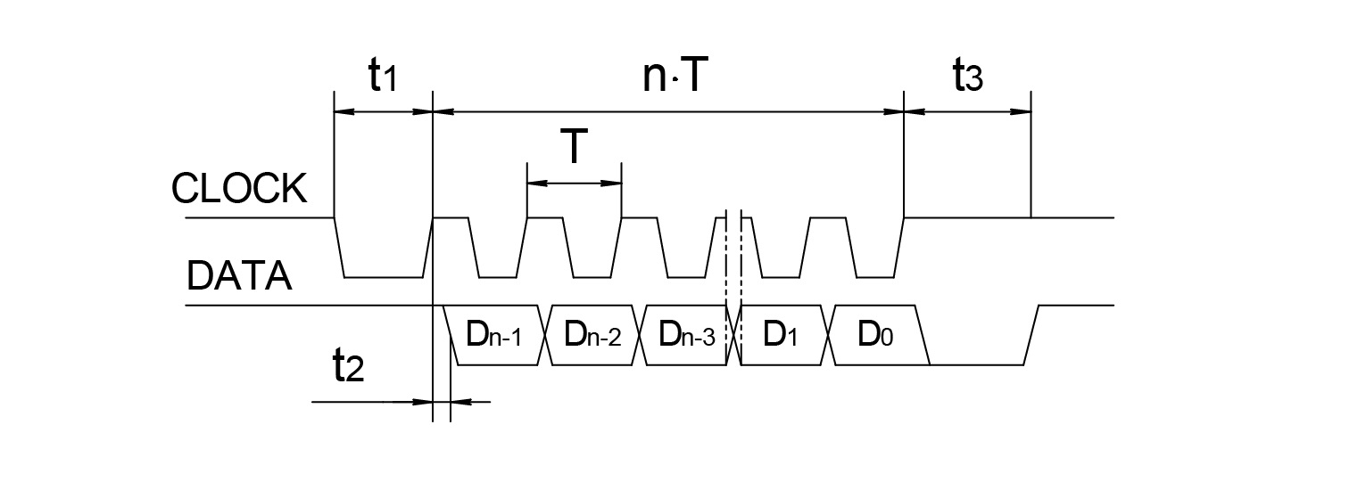
Последовательный SSI
Информация
CLOCKиDATAна рисунке не показаны
CLOCK- входной управляющий сигнал
DATA- выходной сигнал с числом разрядов nT - от 1 мкс до 11 мкс
t1 > 0.45 мкс
t2 ≤ 0.2 мкс
t3 - от 12 до 35 мкс
В исходном состоянии шины CLOCK и DATA установлены в логическую 1. После первого спада CLOCK шина DATA устанавливается в 0 и в преобразователе происходит фиксация текущей позиции.
По фронтам сигнала CLOCK производится побитовая передача зафиксированного значения кода по шине DATA, после чего шина DATA устанавливается в состояние логического 0 и удерживается в нем в течение времени t3.
В этот промежуток времени может быть повторно считано зафиксированное значение кода позиции путем перевода CLOCK в состояние логического 0 и подачи импульса.
Повторение выдачи может производиться неограниченное число раз.
По окончании времени t3 DATA устанавливается в состоние логической 1 и преобразователь готов к выдаче текущего значения позиции.
Если в процессе считывания кода состоние CLOCK не изменяется в течение времени большего t3, то преобразователь автоматически возвращается в исходное состояние.
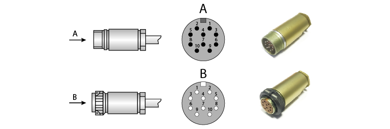
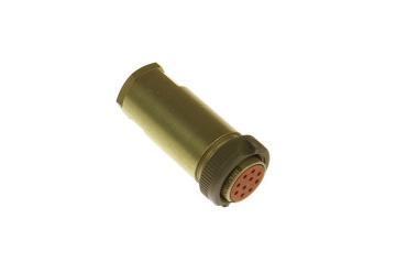
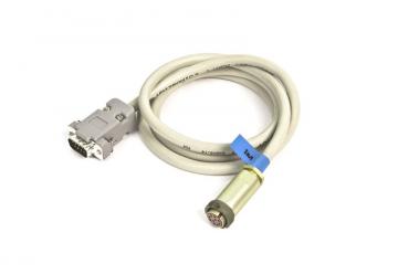
Соединитель РС10ТВ. Последовательный интерфейс:
| Назначение | Clock | Data | Clock | Data | — | — | — | Питание | 0В | Экран |
|---|---|---|---|---|---|---|---|---|---|---|
| Номер контакта | 5 | 3 | 8 | 6 | 1 | 10 | 7 | 2 | 9 | 4 |
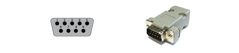
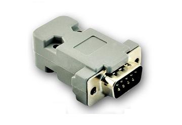
Соединитель DB9. Последовательный интерфейс:
| Назначение | Clock | Data | Clock | Data | — | — | Питание | 0В | Экран |
|---|---|---|---|---|---|---|---|---|---|
| Номер контакта | 2 | 6 | 3 | 7 | 4 | 8 | 5 | 9 | 1 |
Без соединителя. Последовательный интерфейс:
| Назначение | Clock | Data | Clock | Data | Питание | 0В (GND) | Питание* | 0В* |
|---|---|---|---|---|---|---|---|---|
| Кабель 4 пары | Зеленый | Красный | Желтый | Синий | Коричневый | Белый | Розовый | Серый |
| * - дополнительные контакты питания, которые могут быть использованы для контроля и компенсации падения напряжения на линиях питания | ||||||||
Код заказа
| Вариант исполнения | X1 |
| Интервал рабочих температур | X2 |
| Количество разрядов | XX3 |
| Напряжение питания | XX4 |
| Вид выходного сигнала | XX5 |
| Интерфейс | X6 |
| Тип выходного кода | X7 |
| Длина кабеля | XX8 |
| Кабельное окончание | X9 |
| Кабельное окончание | X10 |
| Исполнение по точности (пределы допускаемой основной погрешности) | XX11 |
Пример заказа : ЛИР-ДА190А-3-Н-21-05-RS-3-2-1.0-Р(РС10ТВ)-(±3,5")
ЛИР-ДА190А, исполнение 3, температура эксплуатации - от 0 до +70 ℃, количество разрядов - 21, напряжение питания +5 В, интерфейс - последовательный SSI RS422, двоичный код, длина кабеля 1,0 м, розетка РС10ТВ, допустимая погрешность ±3,5".
| Файл | Размер | Размещен | |
|---|---|---|---|
| Спецификация | 21 окт 2026 |